Effects of the Earth Current Frequency and Distortion on Residual Current Devices


Abstract

Residual current devices characterized by simplicity and cost effectiveness holds a wide range of applications in the protection against electric shock that is one of the important detriments to the safety of human and the performances of electrical apparatus. This article puts the focus on the description of the basic structure and principles of residual current devices, particularly the effect of the earth current frequency and distortion on the mal- and miss operation of electrical apparatus is investigated, which is of reference value for the proper selection of electric apparatus.

Keywords: Residual Current Devices; Electric Shock Protection; Earth Current; Miss Operation; Mal Operation

Effects of the Earth Current Frequency and Distortion on Residual Current Devices

Foreword

Electric shock is caused by flash strick as flashing lighting touch the household electrical wiring, or accidently broken wire touch electrified body , easily lead to electrical equipment damage and cause personal safety accident.

Protection against electric shock is a important method to prevent electric shock. There are several ways:Automatic power off, II equipment, Insulation equipment, electrical isolation; equipotential connection without GND.Automatic power off become the nomalest way to prevent electric shock because of it’s simpleness and operability.As a result, residual current devices with automatic power off technology are more and more widely used.

Residual current devices works by receiving signal,so it works also under other electromagnetic interference signal which called mal operation. When the power swith turn on, it comes out the impact signal cause to the mal operation.The sum of multi-branch electric leakage may lead to override maloperation.When neutral line iterative earthing may cause residual current devices comes to shunt miss operation. When the power leakage happens to the one used by residual current device, it comes miss operation.

As can be seen from the above analysis , the residual current devices have mal operation and miss operation situation in actual use. This article describes the basic structure and principles of residual current devices , focused on effects of the Earth Current Frequency and Distortion on Residual Current Devices in the protection against electric shock.

1.Electric Shock

Most electrocution death and equipment damage accidents are caused by electric shock . Generally speaking, the electric shock accident basically means in terms of electric shock . In accordance with the state of the electrical equipment , electrical shock can be divided into direct contact and indirect contact type.The former is a normal state of electric shock when human touch the charged body,The latter is a shock occurs when people touch the accidently charged body under broken situation but no uncharged normally. Therefore , the former is known as electric shock of normal state , the latter is known as electric shock under breakdown conditions.

According to the way of how people body touch the charged object and the way of how the electric current go through people body, shock can be divided into single-phase electric shock, two-phase electric shock and step voltage electric shock.

single-phase electric shock is mean human body touch the electric conductor in earth or landing, so the partial body of human body touch the charged object lead to electric shock accident. And most shock accident belongs to such kind. The dangerous degree of single-phase shock is related to the operation mode of the electric network. Normally, the single-phase of landing electric net work is more dangerous than UNGND electric network. Two-phase electric shock means the accident that two places in human touch two-phase charged dody , it’s very dangerous. When charged body landing , it’s current go to earth lead to the voltage of GND earth decline. When people closed to earth electrode, the voltage appeared between feets is called step voltage which lead to step voltage electric shock accident. It may appears high step voltage in high voltage broken GND point or beside earth device when large current go through.

IEC 60479-1 defines the four region of A / t relationship , described the morbid physiological effects within each region of the body. As shown in Picture 1 , the horizontal axis represents the current figure flowing through the body , the vertical axis represents current sustained time. Every area shows:AC- 1 zone indicates no perception ; AC-2 area expressed perception ; AC-3 region indicates the presence of reversible effect of muscle contraction ; AC-4 zone may indicate irreversible effects ; AC-4-1 zone may represent cardiac fibrillation up to 5%; AC-4-2 zone represents cardiac fibrillation up to 50%; AC-4-3 zone represents cardiac fibrillation can be more than 50% ;

Each curve in following picture shows : Curve A represents the current perception threshold ; Curve B represents the muscle response threshold ; Curve C1 represents the 0% probability of ventricular fibrillation threshold ; Curve C2 represents a 5 % chance of ventricular fibrillation threshold ; C3 curve represents 50% probability of ventricular fibrillation threshold. Take Curve C1 as an example , when the current go through human body , if the current exceeds 30 mA, the human body is likely to be fatal electric shock unless the current can be cut off in a relatively short period of time.

Picture 1 Regional Rendering of Morbid Physiological Effects

2 Principle of Residual current device

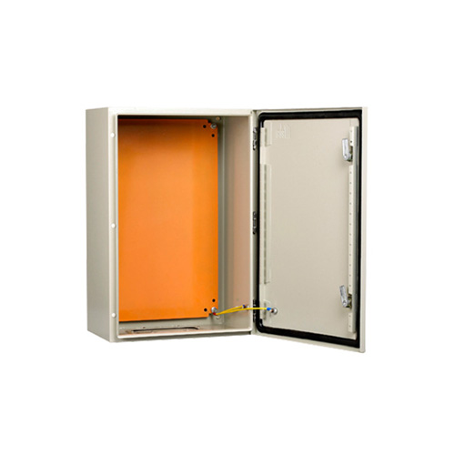
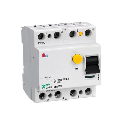
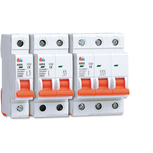
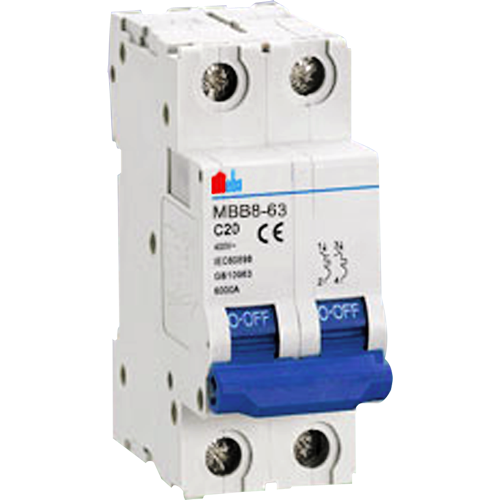
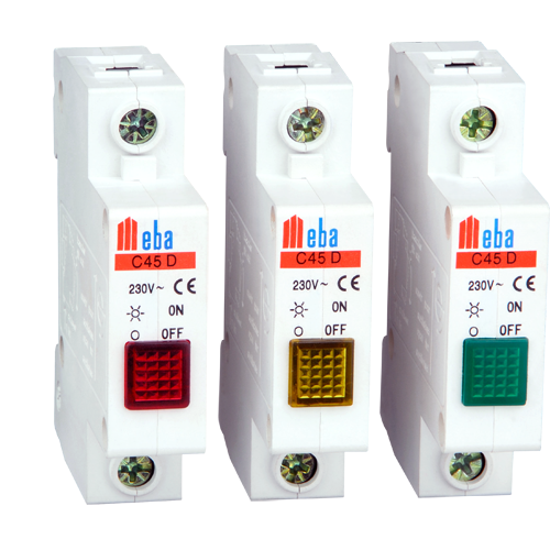
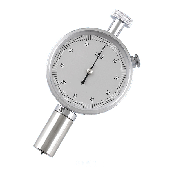
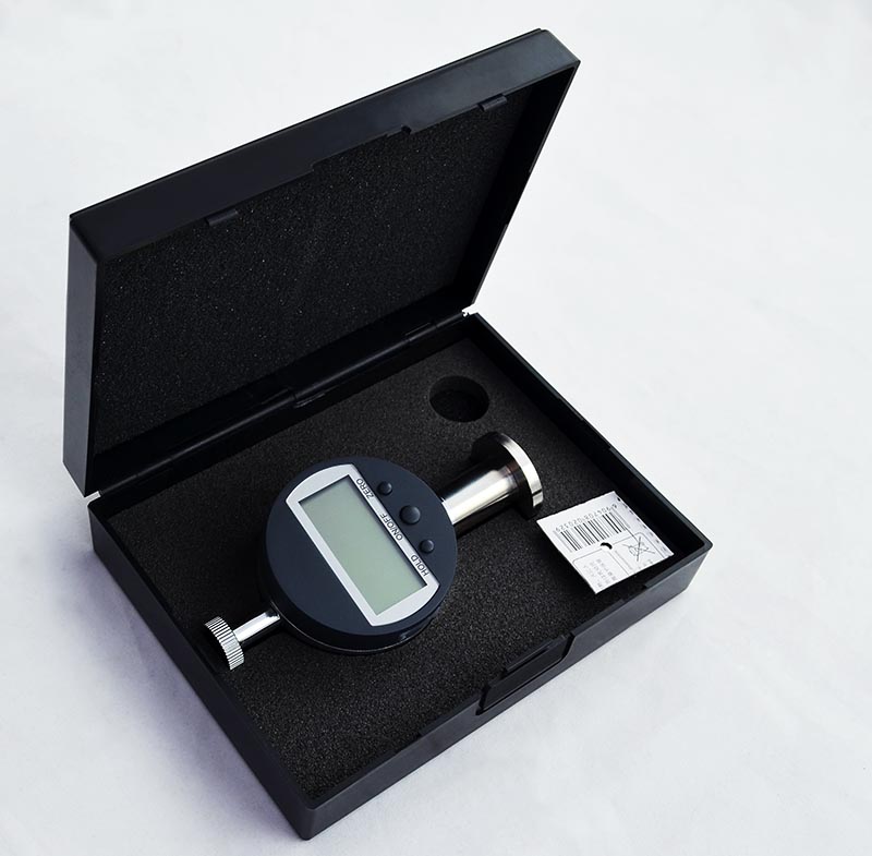
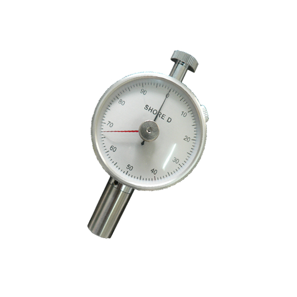
Picture 2 Residual Current Device Appearence

Residual current devices can be divided into two categories: current type and voltage type . Current type is on the basis of error current movement and voltage type is based on error voltage movement. Since the voltage type has characteristics with bad prevention to outside interference ,poor stability and high production costs, such type of residual current devices has been basically elimiated. So the current residual current devices has the dominat position on the research and application of residual current devices in domestic market.

Residual current device used partial residual current from the electric circuit(usually called the residual current) as the movement signal, commonly used electronic component as the Intermediaries. It becomes more and more widely applied with high sensitivity and multiple function. As show in Picture 3, Residual current device is made of 3 parts:

Ferranti transformer (As shown in picture TR): Protected phase conductor L1 , L2, L3 and the neutral line N through the annular core compose transformer’s primary winding.the winding intertwining in the core compose the secondary winding. If no electric leakage, then the current vector sum which go through the three phase conductor and the neutral line is zero. No alternating magnetic field produced, no induced current produced by the secondary winding of transformer.If electric leakage occurs,then the current vector sum which go through the three phase conductor and the neutral line is not zero.The secondary winding of transformer produce induced current and give them to the tripping mechanism for further processing.

Tripping mechanism(As shown in picture WS): includes amplifier , comparator, release and the main switch. The amplifier works for the induced current from the ferranti transformer. the comparator is used to compare the enlarged induced current and the rated residual action current, While the former is larger the release and the main switch work, automatically cut off the power of the error line to protect.

Test button(As shown in picture T):Regularly check residual current device is intact and reliable. Simulate electric leakage ways by pressing the test button to check if it is operating normally .

Picture 3 Residual Current Device Inner Structure

3.Effects of the Earth Current Frequency and Distortion

This section mainly analyzes the protection effects from the current frequency and distortion to the residual current device in the circuit with frequency conversion function.

Picture 4 Earth current waveform in frequency changing circuit

Frequency conversion is generally used to control the speed of squirrel cage electric motor. Figure 4 shows a frequency changing circuit schematic diagram with residual current device(RCD represent in figure 4). Frequency changing circuit is composed of 3 parts: the Rectifier (works for rectifying the waveform input from the power side), the intermediate DC circuit( used to filtering waveform output from rectifier)and the inverter(reverse intermediate DC circuit generates AC DC into the desired frequency). After alternating current through the frequency changing circuit , low frequency current change to the high frequency current. Similarly, the ground analog current frequency increases after go through the frequency changing circuit.

Under the condition of current frequency 50Hz , the perception current threshold is 0.5mA, that is, in such situation , human body has some sense when the current comes to at least 0.5mA. As can be concluded from Figure 1, 10mA cause human body lose muscle control and muscle contraction under 2s consitent current; 30 ~ 40mA lead to ventricular fibrillation and then life-threatening. As for higher frequency current threshold, the threshold of human perception, muscle response and ventricular fibrillation increase accordingly. Figure 5 shows the frequency graph with curve.

1

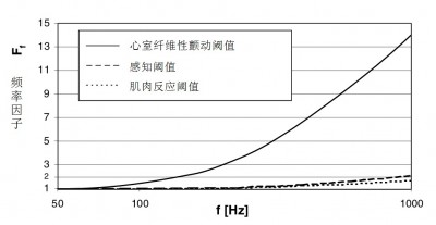
Picture 5 50-1000Hz threshold change coresponsding to frequency

When the frequency is 1000Hz , the ventricular fibrillation threshold goes from 30 ~ 40mA to 420mA. This is very important information , because if the ground current frequency higher than 50Hz, many RCD tripping current increase obviously.

In order to study the effects of ground current frequency to RCD tripping operation, people test several RCDs under the rated residual current ΔIn = 30 mA and 100mA. Figs. 6, 7 and 8 shows the test results under laboratory conditions.

2

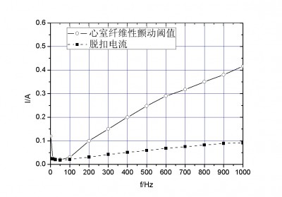
Figure 6 ΔIn = 30mA the AC RCD tripping operation current change

Figure 6 shows the threshold change of the AC RCD tripping operation current and ventricular fibrillation according to the frequency change under ΔIn = 30mA circumstance. The solid line represents ventricular fibrillation threshold varies, dashed line indicates the tripping current varies from 1 ~ 1000Hz. From the figure, comes the conclustion that RCD tripping operation current is decided by ground currnt frequency. When the frequency is higher than 50Hz,tripping current is much smaller than ventricular fibrillation threshold , and therefore, shock occurs the body does not produce ventricular fibrillation in the test frequency range, so AC RCD can play normal protection.

Figure 7 ΔIn = 100mA , A RCD tripping current

Figure 7 shows under the ΔIn = 100mA circumstance ,the changing threshold of A RCD tripping current and ventricular fibrillation fllow the frequency. From the figure the conclustion is that tripping current is much higher than ventricular fibrillation. Therefore, in the test frequency range,the human body may cause ventricular fibrillation when electrical shock occurs, A RCD can not play such a normal electric shock protection.

3

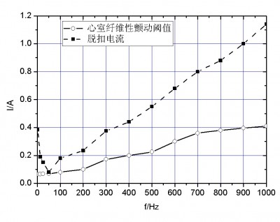
Figure 8 ΔIn=100mA AC RCD current and ventricular fibrillation threshold


Figure 8 shows under the ΔIn=100mA circumstances, short-time delay AC RCD current and ventricular fibrillation threshold change follows the frequency.From the figure the conclustion is that tripping current is much smaller than ventricular fibrillation threshold, that is to say, within the frequency range from 100Hz to650Hz, human body won’t emerge ventricular fibrillation when electric shock occurs, short-time delay AC RCD can play a protection role to such nomal electric shock.

4


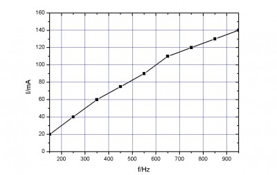
Figure 9 the effect of multiple harmonicwave to the RCD tripping current

The ground current in frequency changing circuit nomally emerge multiple harmonicwave, resulting in waveform distortion. This study shows: the higher of the harmonicwaves,the higher tripping current of RCD. Figure 9 shows under the circumstances,how the multiple harmonicwave affect the RCD tripping current, the actual operation current corresponding to fundamental wave is 65mA.

Study indicates that multiple harmonicwave of ground current may increace the actual operating current of the RCD.

4.Summary

Residual current device can effectively protect the personal safety and electrical equipment when electric shock accident occurs. However, it must be very cautious in choosing the RCD. The change of frequency and waveform in ground current affect RCD’s protective performance. This article study effects of the Earth Current Frequency and Distortion to tripping current, and the conclusion has a certain practical significance for the correct selection of Residual current devices.

Digital Shore Hardness Tester Manual

Shore hardness tester


Digital Shore Hardness Tester Manual


  • overview

Shore hardness tester is an apparatus to measure vulcanized rubber and plastic products. This apparatus has three models of Type A, Type C and Type D,Type A and D respectively are applicable to the testing of low and medium hardness, and high-hardness materials.
Type C applies to the testing of microporous material which is used to make shoes, with compression rate 50 percent, stress 0.049 MPa or above, and this kind of material is made of rubber plastic and has blister in plastic.This hardness gauge conforms to the regulations of GB/T531, GB2411, HG/T2489, JB6148.


二、 Main technical parameters

1、Measuring range:0-100°

2、 Measuring error:Within 20-90°,the error is ≦±1°

3、 Resolution:0.1°

4、 Pressure Needle Range:0-2.5mm

5、End pressure of Pressure Head:Type A and C :0.55N-8.05N Type D:0-44.5N


三、 Using methods

When using sample, one should place the sample in the solid plane, hold the hardness gauge, keep the pressure needle at a distance of at least 12 mm from the edge of the sample,smooth enough pressure in the pressure on the sample, and smoothly press on the sample to a full extent. until pressed to a full extent and contact the sample completely, then read the calibration value within one second.At measuring points which are at least 6 mm away from each other, measure hardness values for five times, and calculate the average value(for microporous material, the distance between the measuring points should be at least 15 mm). In order to keep the stability of conditions and improve the accuracy of determination, one should install the hardness gauge on the same type of the measuring shelf from a complete production network.


四、 Using instructions

1、Before using,please check the hardness tester should be display “00.0” in free state(if don’t display,you can press “ZERO” button).Place the hardness gauge on glass plate, and the pointer should direct at a 100±1 degree angle (the end of pressure needle and the bottom surface of pressure foot should be closely in contact with the glass surface) If the pointer doesn’t point to the zero position, it cannot be used, either. It’s better to send it back to the factory for adjustment.

2 Type D hardness tester on reference plane to check the zero position,Under the heavy load,the hard pressure head is easy to pressed reference plane,so must be put on standard gauge block on the reference plane,when operating with hardness tester,the indenter alignment gage block center hole,then pressed hardness tester,when the indenter foot completely stitching with standard gauge block and reference plane,the hardness tester should be display 10±1HD(Gauge block thickness 2.25 ± 0.0003mm is equal to hardness tester into 10HD pressure depth),if can’t display accurately,the hardness tester also cannot use.

3 Rubber sample shall be prepared according to the requirements of GB/T531;plastic sample shall be prepared according to the requirements of GB2411;Rubber microporous materials sample shall be prepared according to the requirements of HG/T2489.

4 Before the test,rubber sample shall be prepared according to the requirements of GB/T2941,GB/T2918 in the laboratory standard temperature to test.

5 When measuring the sample, A-type hardness gauge’s value is more than 90 degrees, it is recommended that one should use D-type hardness gauge. When using D-type hardness gauge, the value is below 20 degrees, it is recommended that one should use A-type hardness gauge. When A-type hardness gauge’s value is 10 degrees, it is not accurate, and the measurement result can not be used.

6、After complete using the hardness gauge, it should be wiped clean and put into the device box, and stored in dry place to prevent damp. The measurement shelf should be wiped frequently and be coated with a little anti-rust oil to prevent it from rusting, moreover add No. 20 oil to the flexible parts.


Tips on How to Know If You Need To Replace the Distribution Box of Your Septic System

TS-Metal-Box-Stainless-Steel-Distribution-Box

Do you have a septic system that stands alone servicing your home? You possibly do not think much about it and you are being confident that it is working, as it should, at least until there would be something to go wrong and you have found the sewage seeping back to your house into the drains. Unfortunately, this is a familiar scenario for the users of septic systems. The great news is that you can avoid it by having it inspected on a regular basis so that events such as replacing the distribution box and some other problems will be prevented.

These components can very likely be one of the most significant components of the septic systems in the present days. It lies between the drain field and the septic tank, being responsible in channeling the liquid wastewater out into the pipe networks, which leads into the drain field. It placed appropriately when installing the system, it must never be a problem, but if ever it becomes clogged, replacing it will prevent the maintained system from breaking down again. When you install the system, the distribution box need to be placed on the solid, original ground only, and not any portion that was raised as you add fill soil.

If you would replace it on top of the fill soil, there will be the risk, which in some point through the years it will start settling from the weight of the wastewater that is passing through it, making the passage of the water harder if the elevation needs to change. If you have to add fill to the ground that is under it, you can use gravel and not the loose soil. The level gravel will keep it from having to shift around and lose its elevation. The pipes that lead to the distribution box might be at higher elevation slightly, but those that lead out coming from the box through the drain field need to cant downward in order to provide a flowing out into the drain field.

Signs that you need to start backing up

Normal septic maintenance need to keep the tank from becoming too full of the solid meter and only the water need to pass through the distribution box. You need to recognize a foul smell that comes from the water or drains moving slower as compared to the normal things it do when you are draining a tub or sink or you are flushing the toilet. It may be the time to have your box checked for replacement or leveling.

When you install the septic system, the box needs to have water running through it, so as to be specific that it is at an appropriate level, inclining to allow the water to flow through, into the pipes, with no remains inside of it. If it does not, some adjustments should be made before the entire system goes on line. To go through the actions of replacing the distribution box can be a taunting task. To utilize experienced and trained personnel in order to accomplish this will be your best bet.

Get Effective Form of Shock Protection with Residual Current Circuit Breaker

MPFIM4-Residual-Current-Circuit-Breaker

The most largely used residual current circuit breaker or the RCCB are 30 milli-ampere and 100 milli-ampere devices. The 30 milli-ampere RCCB’s current flow is sufficiently small, making it very hard to receive dangerous shocks. Even a hundred milli-ampere is a small figure relatively ac compared to that of the current that could flow on the earth fault with no such protection from the hundreds of amps. A 300 or 500 milli-amperes RCCB can be used in which only fire protection is needed such as the lighting circuits in which the risk of the electric shock is very small.

Characteristics of residual current circuit breaker

  • Both the neutral and phase line wires are being connected through the RCD.
  • It is tripping the circuit when there would be a current earth fault.
  • The amount of current that is flowing through the phase line need to return through the neutral.
  • It is detected by the residual current device or the RCD. Any mismatch between the two currents that are flowing through the neutral and phase are detecting by the RCD, tripping the circuit within thirty mA.
  • If a house would have an earth system that is connected to the earth rod and not the primary incoming cable, then it may have all the circuits protected by the RCD, as you may not be able to get the right amount of fault current in order to trip a MCB.
  • The RCDs are an excellently effective form of protection from shock.

RCCB Limitations

The standard electromechanical residual current circuit breaker are designed for the operation on regular supply waveforms and are not guaranteed to operate wherein the non-standard waveforms are being generated by loads. The most usual is the half-wave rectifier waveform, at times being called the pulsating DC that is generated by the speed controlled devices, computers, semi-conductors, and even the dimmers. The especially modified RCCBs are available to be operated on regular pulsating, AC, and many more.

Furthermore, the RCDs are not offering protection against the current overload. The RCCBs can detect an imbalance in the neutral and live currents. However, a current overload cannot be detected. It is frequently the cause of problems with the novices in replacing an MCB in a fuse box that has an RCB. This can be done in an attempt of increasing protection from shock. If a neutral-live fault occurs such as an overload or a short circuit, the residual current circuit breaker will not trip, and has a tendency of being damaged. In practice, the primary MCB for the premises will possibly trip, or the service fuse, so the situation will most likely not lead to catastrophe, but it can be inconvenient.

You can get an RCD and MCB in a single unit, known as RCBO. To replace an MCB with RCBO with the same rating is generally safe. In the nuisance tripping of the RCCB, sudden changes in the electrical load will cause brief, small current flow to earth, especially in your old appliances. Residual current circuit breaker is very sensitive and it operates very quickly they trip well when the old freezer’s motor switches off. Therefore, RCCB will help you with an effective protection from shock.

Installing a Mini Circuit Breaker

C65N-Miniature-Circuit-Breaker

Mini Circuit Breaker operates just like the normal circuit breaker but its larger counterparts take up half the space of a service panel. This allows you to have 2 breakers at the same time in a space that is normally occupied by one. This makes it very useful in different situations when you are adding new circuit to your fully occupied panel but don’t want to have a new subpanel installed. Miniature circuit breakers are approved and perfectly safe for use according to the national Electrical Code, but adding numerous new circuits without having a new subpanel installed can really be dangerous. Use a Mini Circuit Breaker only in situations that will not make the panel overload.

Replacing and Removing of a Full-Sized Circuit Breaker

  1. Turn the power off at your main breaker. To remove the cover of the panel, unscrew the screws that are holding it in its place. Ensure that you have a flashlight near you as you cut off your entire power at home.
  2. Remove the full-sized circuit breaker by holding the switch and gently pulling it out. You’ll hear the breaker unclip from its hot bar bus without putting so much effort.
  3. Detach the black wire from its screw terminal on the back of breaker through the use of a screwdriver. If you have an internal-terminal type breaker, you have to clip the wire in order to detach the circuit breaker.
  4. Connect the black wire to the terminal of mini circuit breaker and hold it through a switch portion. Snap your mini breaker into the vacated slot of full-sized circuit breaker. In this way, the existing circuit breaker will be replaced.

Adding a New Circuit

  1. Make an access hole on service panel by using a screw and hammer in order to allow the cable for a new circuit.
  2. Put a metal-electrical connector in access hole with an inside locknut and outside screw clamps.
  3. Through the connector, run the cable wire while leaving enough wire length in order to reach the mini circuit breaker’s hot bus bars.
  4. Connect the black wire to the mini circuit breaker and make it snap into its place as what is mentioned above.
  5. Attach the white wire on the neutral terminal bus bar. Also connect the ground-wire to the bus bar ground if it is present, or just leave it as a vacant terminal if there’s no bus ground on the bas bar neutral.
  6. Tighten screw the lock nut on the connector by using the pliers and clamp the cable around by a screwdriver.
  7. Replace the cover of the panel and restore its panel.

Through a mini circuit breaker, the entire faulting condition of your electrical panel can easily be detected. Once a fault is detected, the contacts in the breaker will open in order to interrupt the current flow in the circuit. Some of the miniature circuit breakers are manually operated, so be careful on choosing one that fits your needs and electrical requirements.

How to Wire an AC Contactor?

CLC1-D25-AC-Contactor

Many of the large pieces equipment are directly powered from high lines of voltage. In most homes, these lines are far exceeding the AC standard of 120V. 240V AC and 480V AC are used commonly for large kinds of equipments such as industrials machines, motors and household appliances like dryers and washers. These kinds of voltages must be isolated electrically from the 120V standard AC. The AC contactors are utilized in order to provide the required isolation. They use 120V standard AC power in energizing a magnetic coil that causes several sets of internal contacts to provide and close a high power to equipment. Here are some tips on how to wire a Contactor:

Get the Contactor – Ensure that the contactor contacts are both rated in current and voltage in order to handle the required load of the equipment that is being powered. The contactors can be bought in construction and building supply stores and large hardware stores.

Study the manufacturer information of the contactor – Manufacturer information will determine the 120V AC Contactors Control of 2-input pins and more than two sets of contacts output should be identified. Some of the contacts labeled are indicated as NC (normally closed) and NO (normally open). Also, these contacts are shown as a line drawing from one contact that ends in a dot and the second line from other contact that is near the dot, but doesn’t actually touching the dot. (NO contact)

Check the auxiliary outputs of the contact – Some of the contactors include an output contact as a signal to the circuit’s isolated part that the contactor has energized. This output auxiliary contact of AC Contactors shouldn’t be rated at higher voltage instead, it must be rated at 120V AC.

Route the wires – Remove the entire energy to the wires. Run all of the output and input wires to the contactor. The wires should be rated through the information provided by the manufacturer. Use a wire stripper when cutting out the excess lengths of the wire however, you need to ensure that the wires are long enough in reaching the intended contact.

Strip the wires – By using the wire stripper, strip a half inch from both ends of the wires. If your wire is a stranded type, you need to twist the stripped part in order to ensure that the strands are intact, and no piece is hanging before connecting them in AC contactors. The stray strands can possibly make unintentional contacts with the parts of the equipment which may cause problems and damage.

Wire the auxiliary contacts and inputs – Loosen the screws in contact blocks for wires by using a screwdriver. Insert the wires in to the contact block while making sure that no insulation are attached to the block. Check if there are no stray strands jutting out from contact block. If no stray strands are found, tighten the screws back on contact blocks.

Energize the contactor – Apply the controlled voltage on its input. Listen as the AC contactors click as it engages. De-energize your contactor.

Connect the Outputs – Put each of the stripped ends of the wire into its designated contact block. Just like the way you’ve checked on wiring the auxiliary contacts and inputs, you also ensure that no stray strands are jutting out from its designated contact blocks. Tighten the screws back after you have checked the wires.

Congratulation for Meba brand register in USPTO

6401

[Download not found]

Mark Information

Mark Literal Elements: MEBA

Standard Character Claim: Yes. The mark consists of standard characters without claim to any particular font style, size, or color.

Mark Drawing Type: 4 – STANDARD CHARACTER MARK

Goods and Services

Note: The following symbols indicate that the registrant/owner has amended the goods/services:

Brackets [..] indicate deleted goods/services;

Double parenthesis ((..)) identify any goods/services not claimed in a Section 15 affidavit of incontestability; and

Asterisks *..* identify additional (new) wording in the goods/services.

For: Electrical wire; circuit breaker; electrical relays and transformers; rectifier; power supply; voltage stabilizer, high voltage and low voltage

cabinets, namely, enclosures containing electrical disconnect switches, fuses or circuit breakers used to control, protect and isolate

electrical equipment; electric sensors; Electronic proximity sensors; Distribution board, namely, power distribution units, boxes and

panels; Kilowatt Hour Meters; electrical switches; electrical switches, namely, Electric circuit switches, photoelectric switches,

Electronic proximity switches and Cut-out switches; capacitor; electrical plugs and sockets

International Class(es): 009 – Primary Class U.S Class(es): 021, 023, 026, 036, 038

Class Status: ACTIVE

Basis: 1(a)

First Use: Feb. 08, 2005 Use in Commerce: Feb. 08, 2005

Basis Information (Case Level)

Filed Use: Yes Currently Use: Yes Amended Use: No

Filed ITU: No Currently ITU: No Amended ITU: No

Filed 44D: No Currently 44D: No Amended 44D: No

Filed 44E: No Currently 44E: No Amended 44E: No

Filed 66A: No Currently 66A: No

Filed No Basis: No Currently No Basis: No

Current Owner(s) Information

Owner Name: Yueqing Meba Import & Export Co Ltd.

Owner Address: Houjie Industrial Zone, Liushi, Yueqing,

Zhejiang

Yueqing 325604

CHINA

Legal Entity Type: LIMITED LIABILITY COMPANY State or Country Where

Organized:

CHINA

Attorney/Correspondence Information

Attorney of Record

Attorney Name: Raj Abhyanker Docket Number: 90836

Attorney Primary Email

Address:

[email protected] Attorney Email

Authorized:

Yes

Correspondent

Generated on: This page was generated by TSDR on 2015-08-04 03:26:12 EDT

Mark: MEBA

US Serial Number: 86315451 Application Filing Date: Jun. 20, 2014

Register: Principal

Mark Type: Trademark

Status: Application has been published for opposition. The opposition period begins on the date of publication.

Status Date: Jul. 14, 2015

Publication Date: Jul. 14, 2015

Correspondent

Name/Address:

RAJ ABHYANKER

RAJ ABHYANKER, P.C.

1580 W EL CAMINO REAL STE 8

MOUNTAIN VIEW, CALIFORNIA 94040-2462

UNITED STATES

Phone: 650 965-8731 Fax: 650 989-2131

Correspondent e-mail: [email protected] Correspondent e-mail

Authorized:

Yes

Domestic Representative – Not Found

Prosecution History

Date Description Proceeding

Number

Jul. 14, 2015 OFFICIAL GAZETTE PUBLICATION CONFIRMATION E-MAILED

Jul. 14, 2015 PUBLISHED FOR OPPOSITION

Jun. 24, 2015 NOTIFICATION OF NOTICE OF PUBLICATION E-MAILED

Jun. 09, 2015 LAW OFFICE PUBLICATION REVIEW COMPLETED 66121

Jun. 08, 2015 APPROVED FOR PUB – PRINCIPAL REGISTER

Jun. 08, 2015 TEAS/EMAIL CORRESPONDENCE ENTERED 66121

Jun. 08, 2015 CORRESPONDENCE RECEIVED IN LAW OFFICE 66121

May 29, 2015 TEAS REQUEST FOR RECONSIDERATION RECEIVED

Feb. 19, 2015 NOTIFICATION OF FINAL REFUSAL EMAILED

Feb. 19, 2015 FINAL REFUSAL E-MAILED

Feb. 19, 2015 FINAL REFUSAL WRITTEN 82421

Jan. 28, 2015 TEAS/EMAIL CORRESPONDENCE ENTERED 66121

Jan. 28, 2015 CORRESPONDENCE RECEIVED IN LAW OFFICE 66121

Jan. 20, 2015 ASSIGNED TO LIE 66121

Jan. 09, 2015 TEAS RESPONSE TO OFFICE ACTION RECEIVED

Sep. 29, 2014 NOTIFICATION OF NON-FINAL ACTION E-MAILED 6325

Sep. 29, 2014 NON-FINAL ACTION E-MAILED 6325

Sep. 29, 2014 NON-FINAL ACTION WRITTEN 82421

Sep. 29, 2014 ASSIGNED TO EXAMINER 82421

Jun. 27, 2014 NEW APPLICATION OFFICE SUPPLIED DATA ENTERED IN TRAM

Jun. 24, 2014 NEW APPLICATION ENTERED IN TRAM

TM Staff and Location Information

TM Staff Information

TM Attorney: LEWIS, SHAILA E Law Office Assigned: LAW OFFICE 114

File Location

Current Location: PUBLICATION AND ISSUE SECTION Date in Location: Jun. 09, 2015

How to Use a Molded Case Circuit Breaker?

NS-160N-4P-Moulded-Case-Circuit-Breaker

The conventional molded case circuit breaker utilizes thermal magnetic or electromechanical trip units which are interchangeable or may be fixed. MCCB can provide a protection by using the combination of an electric sensitive electromagnetic device and a device sensitive to temperature. These two devices can act mechanically on trip mechanism.

The use of MCCB will depend upon the required protection and application. It will use one of different combinations of the trip elements in order to protect against different certain conditions which includes:

  • Thermal Overloads – In a thermal overload condition, there is a build-up temperature between the conductor and the insulator. If it is left unchecked, the life of the insulator will reduce drastically that may result to short circuit that’s why a molded circuit breaker is used.
  • Short Circuit – This usually occurs when there’s an abnormality on the electric flow which is very high than usual. As a result the insulation of the system fails. In order to stop the immediately stop this kind of current flow to avoid major damages, instantaneous element or short circuit of MCCD is utilized.
  • Ground Fault – This is actually categorized as a short circuit, the only difference is that it is phase to ground, which is probably the most common fault type on the low voltage systems.

Usually, the arcing ground fault current aren’t large enough for molded case circuit breaker protected device to be detected. If it is left undetected, the tripping of standard protective device can sufficiently increase. Usually, under this kind of situation, it is already too late and major damages are already done. A good example of this is a motor that have an internal failure on insulation. Even a very small current flow must be identified and eliminated before the major damages on the motor takes place.

The protection devices for ground fault were used nowadays in order to provide an extra protection level. In today’s modern circuit breakers, ground-fault protection device are now integrated as a part of molded case circuit breaker trip unit.

Trip Overload Action

Thermal trip or overload action utilizes a bimetal piece that is heated through load current. Actually, this bimetal is two strips metal that are bonded together, and each of them has different thermal heat rate expansion. They’re not field adjustable but factory calibrated.

Trip Short-circuit Action

Trip short circuit action utilizes an electromagnet that has a winding series with load current. When short circuit occurs, the flowing current through circuit conductor causes the strength of electromagnetic field to rapidly increase and attract more armatures. When this situation happens, the trip bar will rotate due to armature that will cause the molded case circuit breaker to trip.

Trip Thermal Magnetic Action

As what the name implies, this trip action combines the magnetic unit and thermal unit features. As a result the current time curve combines that characteristics performance. A trip thermal magnetic unit is perfectly suited to almost all general purpose application because of its temperature sensitive and automatic safe follow cable and loadings of equipment. These kind of loadings can differ in ambient temperatures. The thermal-magnetic units don’t usually trip if overload condition is not really dangerous, but will instantly trip with very strong short-circuit currents.

How to troubleshoot AC Contactor

LC1K0910-AC-Contactor

Contactor is known to be the one responsible in relaying switch which sends   the electricity into your AC’s compressor. It pulls all of the electrical contacts from each other whenever the power is needed and at the same time, close contacts in order to power up something. When it fails, the compressor in return cannot send the needed refrigerant. If this occurs, either, it will keep your unit operating simultaneously or it will be preventing it to operate again. This all depends on whether your contacts are close or open if the circuits failed.

Simultaneously Running AC

Go and open up your air conditioning unit and better found out where the contactor is located. But to make sure check this out first on different sites so you are familiar on how it really looks like. Then after then check if the AC contactor is clean             . Most of the time, insects, grime and even dirt are the one responsible   on the failure of the contactor. Most of us pay hundred dollar and even more of it, just to wipe those spider webs by an electrician.

When the contactor are clean though, however, if it looks like burned or welded, it is an indication then that you already need to replace it. Make sure that you power off first your circuit breaker before detaching or installing the new contactors.

Air Conditioning is not Running properly

If this happen, you better look on both side of contact points. This is the time you will see strips of metal, which is connected on the wiring and the contacts, leading to the motor of the air conditioner. These certain strips are known to be overload heaters, which functions, similar way as the fuse. When there is too much electricity flowing from them, they will melt and at the same time the power supply will stop. As soon as you visually inspected it and you see that one of it melted, you really need to buy a new one and install it right away. But if your newly installed contactor melted, then most probably, you are receiving too much voltage coming from contactor. It is much better if you will consult your manual for the necessary voltage that is around 24 volts. Whether you get too much or insufficient amount of voltage, you must immediately replace your contactor.

What you need to consider?

If you are replacing contactors,   why don’t you try t have some model and make like the original. If it is not possible, make sure to have one terminal, which are similar on the one that you took from the air conditioning unit. Ensure yourself that the voltage rating is also similar as what the lad capacity do have. You may find it out by means of the literature, which comes from the new purchased contactors, or through discussing with the salesman you bought from. These are some troubleshooting tips you can have with your AC contactor.

How to replace molded case circuit breakers

MCCB-&-MCB-Moulded-Case-Circuit-Breaker

Conventional molded case circuit breakers utilize thermal magnetic or electromagnetic trio units, which may be interchanged or fixed. It also gives protection through the combination of the devices, which are sensitive into temperature. These devices take action on the trip mechanism mechanically. Molded case circuit breakers are being rate based on the rms ampere at a certain ambient temperature. But, there are instances that you already need it to replace. The following are the things you have you have to consider if you planning to do one.

Significance

Resetting a particular circuit breaker is like turning on the switch of the light. Over protection devices and small flips can be then reused and reset on couple of times.   This is a kind of reliability, which allows numerous numbers of homeowners to save time and money while not replacing a specific blown fuse.

History

In replacing a glass cylindrical fuses, this useful device, molded case circuit breakers, introduce new cost saving and reliable ways. In some points, when a fuse is blown, they need to replace it because the electrical power would be reinstated in a certain circuit. Several instances though, the fuse will be blown again and the issue may be not addressed. On the other hand, molded case circuit breakers are not going to have a problem then with one-time usage.

Function

Molded case circuit breakers are being manufactured specially for the end users to not access anymore with internal workings on the over current protection device. In general, those constructed two pieces of insulated plastics, which are electrically heavy duty, are captivated in order to form a whole. Within the shell plastic shells are the series of the thermal components as well as spring loaded triggers. If the thermal components gets too hot, from the over current circumstances, spring will trip and the electrical circuit will shut down.

Sizes

Molded case circuit breakers may range in sizes from 15 amperes for the houses and basically amperes for the commercial and industrial equipment and settings. Bigger industrial breaker may enclosed metal cabinet two times of the common refrigerator which can be found in your house.

Types

In large industries, molded case circuit breakers may also have that adjustable setting which involves the face of the particular device. It is generally being used for higher amperes, something like 100 amperes or more than that. When spikes happens, these main circuit breaker can be then adjusted to start equipment.

Above mentioned are few things you have to know before you replace your molded case circuit breakers. Circuit breakers which serve as the switch or the control device should be also properly given attention since it is also part of the electrical system. If your electrical system in your house is not properly replaced, there’s a chance that your you and your family’s safety is at risk. Would you wait for something terrible to happen? Of course not. It is better that you know how to prevent things to happen rather than regret at the end.

How to replace AC contactor

C3RT1015-AC-Contactor

AC contactor pertains to the switch, which can be found on the outdoor part of the AC unit. This switch is comprised of metal plunger, control coil as well as one to two electrical contact sets.  Switch turns on and off AC units whenever you needed it while keeping your house on your desired temperature.

But, in some instances, contactor may fail and this may result for the condenser to stay on perpetually.   For practicality purposes, it is much better if you will replace your AC’s contactor in order to fix this issue. Here are the procedures, which may help you replace it:

  1. First, you must turn off your circuit breaker for your safety. Basically, it supplies efficient electricity into the air conditioning unit right on the main panel of electricity. As much as possible use circuit tester that is non-contact outside so you can confirm effective shutting down of the power. Never try to contact the contactor while the power is on. You might experience electrocution.
  2. Detach the screw, which secures side panels from outside of the AC unit through the help of the screwdriver. Repeat this process if it is necessary.
  3. Carefully lift up the topmost lid of the unit and set it aside. Remember, this may be too heavy for you so it is better if you will ask a help from your friend.
  4. Then, after that, look for the contactor within the AC unit. Usually, it looks like a black box wherein several are attached. Every manufacturer of contactor employs various types of wire configuration according in their desired designs.
  5. Make sure that you take note the wire configuration on single piece of paper.   Jot down the position of every wire as well as the colour so you can still attach it again on the configuration on the new and fresh contactor.
  6. Remove the contactor through your bare hands. They must slide down on the contact of the contactors.
  7. Get rid of the screws, which secure the contactors from the AC unit through screwdriver. Put the contactor on it.
  8. Then after that, it is now time for you to reverse procedure 6 and 7 for the installation of the new contractor.
  9. Afterwards, you should also reverse procedure 2 down to 4 so you can reassemble your Air conditioning unit.
  10. Next, bring back the power by turning it on from the circuit breaker.
  11. Finally, you should   try out your AC unit so you can make sure that it is working correctly. Set its temperature into ‘cool’. Let the system do it cycling process such as on and off. This will verify that your newly attached contractor is now performing accurately.

While you are replacing it, you must use caution around with the interior of your air conditioning unit. Never damage or bump any similar components like coils. There’s a possibility that they system will not function appropriately if its parts are damaged.

How to Install Mini Circuit Breakers

meba-mcb-MB8

How to Install Mini Circuit Breakers

Mini circuit breakers are specifically designed   for the protection of lines and cables against short-circuit and overload. Therefore, it provide the care for the electrical equipment against massive temperature rise and damage when short circuit occurs. It operates the same ways as the larger one however, it only takes half space in the service panel.

However, don’t you know that installation of mini circuit breaker is one of the most daunting electrical work known so far?   Yes, but there are certain ways on how to install thing safely and effectively. Here’s how:

  • Prepare first the things that you will need. These include screwdriver, flashlight, wire stripper, wire cutter, hammer, two miniature breakers, pliers and metal connector.
  • Start it through turning off the power from the panel in the main breaker. Detach its panel cover through removing those fasteners, which is holding it in its place. Make sure that the flashlight is near you since you are going to turn off everything in your house.
  • Take away that full sized breaker through grasping the switch and then pull it gently. This will unclip effortlessly from the bus bar.
  • After that, you should disconnect that black wire located at the back of the breaker from the screw terminal through the power of the screwdriver. When the breaker is one type of the internal-terminal,   then this is the time that you are obliged on disconnecting the breaker in order to clip wires.
  • Attach the wire into the terminal of the mini circuit breaker. Then afterwards, hold it through the switch portion. Break the breaker in the slot situated in the full size breaker. It will then replace the existing circuit.

To add the new circuit, you must:

  • Make a hole so you can have an access in the service panel with a certain hammer as well as screw that let the cable for your new circuit.
  • Next, you can no install the metal electrical connector into the access hole along with the locknut within and screw lamps for the outside.
  • Start to run the cables by means of the connector wherein you need to leave behind sufficient amount of wire so it can reach the bus bars. Wrap up then the cable on the box’s interior edge       to prevent other kinds of cables and be able to access right away the hot bus bars.
  • Place cables black wire into the mini circuit breaker and the snap it right to the exact as prescribed.
  • You now need to connect those white wires into the terminal in the neutral bus bar which is also known as white too. Then connect ground wire through bus bar if this is present. This is usually comes in green.
  • Tighten up lock nuts in the connector through clamps and pliers in the cable by means of screwdriver.
  • Lastly, you may now replace the cover of the panel and bring back the power on it.

Your safety and security must be observed all the time whenever you are installing mini circuit breaker or any other electrical works that you have to do. Remember, your life is more important than any other things.


How to fix a mini circuit breaker


meba-Breaker-C45N

Circuit breakers   are the one responsible in turning off the process of flowing of the electricity into the circuit if any kind of fault happened. This breaker is strong and don’t usually caused any tripped circuits. It is also considered as heat sensing switch that employs bimetal strips as well as springs in order to close a certain circuit. This allows smooth flow of the current. On the other hand, faults are there to create heat that causes strip to bend down. It releases the lever, which opens circuit and cut off the power not unit you set it again. You must start troubleshooting right at the endpoint of the circuit and not on the breaker.

Before doing that, prepare the things that you will need on your fixing job. It includes new circuit breaker, screwdriver as well as electric receptacle tester.

  1. First thing first. You must check if there’s any overload circuit. Many circuits are operating at 15 amps and 120 volts and do have the capability of drawing out 1,440 watts safely and effectively. When the total number of the wattage in the circuit exceeds, there are possibilities that the breaker would trip.
  2. You can check for short circuits through unplugging the appliances or fixtures one by one and watch out for the breaker if it will stay close as soon as your reset that. It will determine the appliance that is the causing electrical problems.
  3. Assess every power receptacle and at the same time, light switch on the circuit for any worn or loose wires. Oftentimes, overheated wires is most of light fixtures are considered culprits.
  4. Identify faults right on the power outlets through the help of the neon receptacle analyser. When there’s no short on outlets and switches, most probably, the problem lies in on the wiring or on the breaker.
  5. Immediately replace the breaker prior on calling for some professional help in order to check your wires. Shut down the power to the main panel before you pull the breaker off the bar. You are going to get a nasty electroshock when the power is not yet off. Also, you should disconnect that so called black wire which leads into old breaker and then after that, attach it to circuit breaker. Afterwards, snap out the new breaker right on the place.
  6. If the steps above doesn’t work out, this is the best time for you to call an electrician.

As soon as you’ve learned that there is something wrong with your circuit breakers, you have to do something. However, you must also consider if you really have the right knowledge or if it much better if you will ask an expert assistance. Always keep in mind that electrical problems require an immediate attention or else you might take you and your loved one’s life into possible danger. Aside from that , it would be good for everyone to live without bothering about their safety.


How to buy the Right Circuit Breaker

meba-mcb-MB8

Circuit breaker is specifically designed to be the switch in shutting off automatically in case of shortage or overload. It helps on preventing accidental electrocution as well as electrical fires.

In case of rewiring of an old building, oftentimes, new circuit breakers are being added in order to substitute older set ups. In addition to this, if you are building new construction, anything is then wired into a circuit breaker within the electrical box in a certain business or home. Alternatively, several people pertains circuit breakers as breakers or trips.

If you want to seek the right mini circuit breaker for business or home application, it is then essential if you know and understand the variance of its kind. When a contractor or consumer is informed about the kind of the circuit breaker needed   in a specific project, looking for them is easy then. Everyone could buy circuit breakers by means of the online world. The following are useful tips when you are planning to buy circuit breakers.

Determine the type of Circuit Breakers you need

You must be able to identify the right circuit breaker that you will need.   Basically, there are three types of circuit breakers. Residual current devices or RCD are specifically designed for isolating supplies to protect socket-outlets, circuits or electric equipment in case of flowing down to earth. On the other hand, mini circuit breakers actually provide the protection against overload as well as short circuit. Lastly, residual current breakers with overcurrent protection are the devices, which are combined MCB as well as RCB’s circuit.

Identify the right number of poles

You have to choose an accurate number of poles to give the right protection. MCB and RCD are then available in a range of 1-4 poles.

Know the current rating requirement

In every AS/NZS 3000 rules in wiring, current rating of the circuit breakers must not be greater than of the cable-current carrying capacity. It must be equal or greater than the highest maximum current of the system’s capacity.

Choose the voltage of the network

Nominal voltage for Safe-T devices, DIN-T as well as MOD6 is none other than 240V/415V. But please watch out for any technical data to on every item in questioned.

Know the minimum breaking capacity, which is needed

Based on the wiring rules, protective devices, which are providing the protection against short circuit and overload must have the capability of breaking any types of overcurrent. It includes potential short circuit current on certain points wherein the devices are being installed.

Choose the trip sensitivity that is required

Trip sensitivity or rated residual operating current of the RCD is known to be the lowest level of the leakage current, which is necessary in operating device. Choosing of trip sensitivity requires you to take account on the purpose of RCD.

Choose the Brand type suited on your situation

There are various differences among the brand types. This explains why it is much better if you will go research first before you go out and buy.


All You Need to Know About Mini Circuit Breaker

meba-Indicator-C45D

Have you ever wondered what a mini circuit breaker is? They are unique breakers with a very wide range of uses for electrical purposes. The electrical switches that automatically turn off the flow of electricity when a problem is identified within the electrical circuits are called the circuit breakers. The MCBs are typically used in different electrical units of the small commercial premises, domestic residence and commercial premises. The MCBs are the ones that protect and control the electricity supply of several electrical circuits installed in these buildings. The electrical circuitry are protected from danger of damaging from the overcurrent conditions if and when ones should develop.

Housing of Mini Circuit Breakers and Their Work

Din rail of a miniature circuit breaker is a very wide metal-rail shaped just like a hat with cross section when breakers are typically mounted. Usually, the standard size of din rail is 35mm and the mini version measures 15 mm by 5.5mm, and the largest version can size up to 75mm wide. The MCBs are often single-pole breakers which are designed to be placed in a metal-looking cabinet that can house many piece in one place at the same time. Usually, the housing of mini circuit breakers come with a movable handle that comes out into 1 of 3 positions: tripped, on or off. Either automatically or manually, this switch or handle can actually be reset so that the normal operations of electricity can be resumed unlike the fuses which can only be used once and after which must be discarded.

Tripping mechanism of MCBs instantly respond to very high electrical overload current with magnetic trip or/and respond to the continuous over-current at the current’s lower levels, which don’t automatically trip the circuit breaker but can possibly cause a system damage if it is persisted. Mini Circuit Breakers are just the same on how a surge protector works, with its capability on thermal trip. A great example of a persistent low level flow of over-currents is during a very strong thunderstorm and the power keeps on blinking on and off. During this kind of situation, or when an overload or short circuit is perceived, the breaker will “break” the current flow in order to protect the electrical units system.

What is Impedance and how does it affect the electrical circuits?

The earth’s surface has varying degrees of electrical potential from one place to another, as well as under numerous physical conditions. A place on earth with high impedance has a greater risk of having shocks within a metal piece equipment. These kinds of changes in electric current are not strong enough to trip the mini circuit breakers but powerful enough to kill or harm a person. Leakage electric circuit breakers are used to sensitive event the small amounts of electricity lurking in a piece of metal equipment. Nowadays, along with MCBs, the ELCB are also used in order to ready for such situations. This kind of circuit breaker can detect any imbalance between a current leaking and energized circuit through a grounded body of a person to prevent potential lethal shocks from happening.

Wire terminal pulling-out force tester

  • Introduction:

ADL Terminal pull force tester is a kind of testing equipment to wiring harness and electronic industry, specifically used to test all kinds of wire terminals pulling-out force. The instrument can combine NK, HF force gauge and special fixture in testing. This instrument has characteristics of compact device,accurately controlling, high testing accuracy, convenient specimen clamping, simple operation, etc. It is the ideal equipment for wiring harness factory to ensure product quality.

  • Instrument introduction
  1. The base of instrument(As shown below)1
  • Horizontal installation
  • Manual operation, simple and stable.
  • This machine can be installed on the table (platform) to make the frame more stable to use.
  • Size: 45cm×26cm×16cm
  • Effective stroke: 50mm
  • Rated load: 500N (Can also be configured 1000N)
  • Net weight: 10.6Kg
  • The force gauge of the instrument:

The standard configuration of Terminal pull force tester is with digital force gauge (HF-500),you can also config with analog force gauge(NK-500), the price is different.


  1. Digital force gauge
  • Type: HF—500
  • Load:500N(Kg、N and Ib three units can be converted automatically)
  • Resolution: 01N
  • Precision: ±0.5%
  • Output interface: RS 232 Nine holes socket
  • Charging power: 110-220V/AC, Batteries continuous working time: 6-8 hours
  • Stability: temperature drift: 2uV/℃(0~60℃); null drift: ≤ 0.1%/8hours/FS
  • Calibration range: Full range calibration
  • Environmental temperature: 0~+60℃
  • Environmental humidity:≤ 80%
  • Allow overload: 150%
  • Supply power mode: No. 5 Ni-MH battery, 220V AC, charging for 4-6 hours
  1. Analog force gauge
  • Type: NK—500
  • Load:500N(50kg)
  • Push pull rod trip: 10mm
  • Working temperature: 20℃±10℃
  • Transportation temperature:-27℃~+70℃
  • Relative humidity: 15%~80%RH
  • Working environment: No seismic focus around and corrosive medium.


Customers can according to requirements to configure different kind force gauge:

Specifications of analog force gauge: NK—10、20、30、50、100、200、300、500

Specifications of digital force gauge:HF—2、5、10、20、50、100、200、500、1000 etc.

  1. Instrument left fixture
  • Size: 115mm×180mm×30mm
  • Applicable scope: mainly used in Mating &Unmating Force Test and wire terminals pulling-out force testing.
  • Standard load: maximum. Load: 1000N
  1. Instrument right fixture
  • Type: AJJ-06
  • Applicable scope:Various cables, glass, leather, various electric components etc. material’s tension tests,collapsing force tests, strength tests slide, terminal testing and so on.
  • Standard load: 500N, Maximum. Load: 1000N
  • Instrument installation method
  • The installation method of base

This instrument can be installed on the table to make the instrument more stable. Please ensure that the working plat is horizontal, to make the testing more accurate. When installation, please refer to(Longth x width: 430mm×80mm, 4 M4 tapped hole)

  • The installation method of force gauge
  • Use the M4 wrench to loosen the 4 M 4×16 hex socket screws on the force gauge mounting plate, unscrew the force gauge mounting plate.
  • When installing HF series digital force gauge, using the M4 allen wrench to make the 4 pieces M4×10 hex socket screws in the accessory bag pass through the 90×40 holes on the force gauge mounting plate, screwing into the 4 M4 tapped hole, install the force gauge onto the mounting plate. Or using the cross screwdriver make the 4 pieces M3×10 cross recess head screws in the accessory bag pass through force gauge, to install the force gauge onto the mounting plate. Screwing the 4 pieces M3 into 145×30 hole on mounting plate.
  • When installing NK series analog force gauge, unscrew the 4 pieces M×10 screws by cross screwdriver, to make the 4 pieces M3×14 cruciform slot screws pass through the 145×30 mounting holes on mounting plate, screwing into 4 pieces M3 tapped holes(unscrew M3×10 screws).
  • After installing the force gauge, using M4 socket head wrench to install the force gauge mounting plate on the test stand again.
  • The installation method of left fixture

Using the M4 socket head wrench to make the 4 pieces M4×10 socket head cap screws in the accessory bag pass through the 4 regulation holes on left fixture mounting plate, screwing into the 4 M4 tapped holes on the test sand base plate.

  • The installation method of right fixture

Screwing the M6 screw nut in accessory on the force gauge rod, then screw the right fixture on the force gauge rod,adjust the M6 screw nut to make the right fixture contact firmly.

  • General test procedure
  1. Put one end of wire connecting terminal into the mouth of left fixture, turning handle to clamp the wire part(end of wire connecting terminal has been pressed)
  2. Put the other end of wire connecting terminal into the mouth of right fixture, turning handle to keep the end of wire connecting terminal stucking in the middle.
  3. Aiming the left fixture centre at right fixture centre by M4 socket head wrench.
  4. If installed the HF series digital force gauge,turn on the power,when the LCD display zero is ok.
  5. If installed the NK series analog force gauge, press the switch button to make it turn to Zero.
  6. Turn the handle, make the left fixture move left, and make the right fixture lock the terminal.
  • Daily maintenance and maintenance
  1. Do not use overload, the instrument rated load is 500N .
  2. Note the daily maintenance work, maintain equipment parts clean.
  3. When the machine go wrong, please contact manufacturer or the place you bought( Do not Remove and repair unauthorized).

Digital Shore Hardness Tester Manual

Digital Shore Hardness Tester Manual


  • overview

Shore hardness tester is an apparatus to measure vulcanized rubber and plastic products. This apparatus has three models of Type A, Type C and Type D,Type A and D respectively are applicable to the testing of low and medium hardness, and high-hardness materials.
Type C applies to the testing of microporous material which is used to make shoes, with compression rate 50 percent, stress 0.049 MPa or above, and this kind of material is made of rubber plastic and has blister in plastic.This hardness gauge conforms to the regulations of GB/T531, GB2411, HG/T2489, JB6148.


二、 Main technical parameters

1、Measuring range:0-100°

2、 Measuring error:Within 20-90°,the error is ≦±1°

3、 Resolution:0.1°

4、 Pressure Needle Range:0-2.5mm

5、End pressure of Pressure Head:Type A and C :0.55N-8.05N Type D:0-44.5N


三、 Using methods

When using sample, one should place the sample in the solid plane, hold the hardness gauge, keep the pressure needle at a distance of at least 12 mm from the edge of the sample,smooth enough pressure in the pressure on the sample, and smoothly press on the sample to a full extent. until pressed to a full extent and contact the sample completely, then read the calibration value within one second.At measuring points which are at least 6 mm away from each other, measure hardness values for five times, and calculate the average value(for microporous material, the distance between the measuring points should be at least 15 mm). In order to keep the stability of conditions and improve the accuracy of determination, one should install the hardness gauge on the same type of the measuring shelf from a complete production network.


四、 Using instructions

1、Before using,please check the hardness tester should be display “00.0” in free state(if don’t display,you can press “ZERO” button).Place the hardness gauge on glass plate, and the pointer should direct at a 100±1 degree angle (the end of pressure needle and the bottom surface of pressure foot should be closely in contact with the glass surface) If the pointer doesn’t point to the zero position, it cannot be used, either. It’s better to send it back to the factory for adjustment.

2 Type D hardness tester on reference plane to check the zero position,Under the heavy load,the hard pressure head is easy to pressed reference plane,so must be put on standard gauge block on the reference plane,when operating with hardness tester,the indenter alignment gage block center hole,then pressed hardness tester,when the indenter foot completely stitching with standard gauge block and reference plane,the hardness tester should be display 10±1HD(Gauge block thickness 2.25 ± 0.0003mm is equal to hardness tester into 10HD pressure depth),if can’t display accurately,the hardness tester also cannot use.

3 Rubber sample shall be prepared according to the requirements of GB/T531;plastic sample shall be prepared according to the requirements of GB2411;Rubber microporous materials sample shall be prepared according to the requirements of HG/T2489.

4 Before the test,rubber sample shall be prepared according to the requirements of GB/T2941,GB/T2918 in the laboratory standard temperature to test.

5 When measuring the sample, A-type hardness gauge’s value is more than 90 degrees, it is recommended that one should use D-type hardness gauge. When using D-type hardness gauge, the value is below 20 degrees, it is recommended that one should use A-type hardness gauge. When A-type hardness gauge’s value is 10 degrees, it is not accurate, and the measurement result can not be used.

6、After complete using the hardness gauge, it should be wiped clean and put into the device box, and stored in dry place to prevent damp. The measurement shelf should be wiped frequently and be coated with a little anti-rust oil to prevent it from rusting, moreover add No. 20 oil to the flexible parts.

LX-D-1 新款数显 LX-D-2

How to use digital caliper

Digital Caliper Instruction Manual

Digital caliper

  • Diagrammatic Structure
  1. Internal jaws   2. Inch/mm key     3. Locking screw   4.LCD display     5. Depth measuring blade   6. Scale     7. Battery cover     8. “Zero” key 9. “on/off” key       10. External jaws
  • Characteristics & Function
  1. LCD readout display, with four measuring functions of inner diameter, outer diameter, depth and step.
  2. It can work in both direct measurement and relative measurement.
  3. It is made of hardened stainless steel material with advanced technology and excellent manufacturing.

4.Its complete sealed module structure, provides it with certain resistance to water, oil and coolant.

  1. USB interface allows data to be outputted to a printer or computer for data processing and printing.


  • Usage Direction
  1. Put the specially equipped battery cover key in the middle of the battery covergroove, rotate counterclockwise, open the battery cover, and install/replace battery, then rotate clockwise to lock the battery cover.
  2. When the LCD readout displays small fonts “in” , it is under inch system.
  3. Mm/in: it is a Metric and inch conversion key. Press this key for mm/in system
  4. ZERO: Zero Setting key. It can set-zero in any position within the measuring range.
  5. ON/OFF: power on/off key.
  6. Before usage, loosen the fastening screws on caliper frame, and pull the caliper frame open gently, then use a clean soft cloth to wipe the measuring surface and the guiding surface clean.
  7. Check the “zero” position: Push the caliper frame gently until the two measuring jaw surfaces are close, so the LCD readout displays “zero”, otherwise, press the “zero” key to set- zero.
  8. When measuring outside diameter,fix theoutside measuring surfacesclose to the measured workpiece.
  9. When measuring inside diameter, put the measuring jaws under measuring in the diameter direction,don’t lean.
  10. When measuring the depth, put the depth measuring blade vertically with the measured workpiece’s bottom surface.
  11. Direct measurement: use the caliper to measure the workpiece directly, and the LCD readout displays the measuring value
  12. Relative measurement:set “zero” when measuring the standard workpiece/sample, then measure the workpiece, the LCD readout displays the relative measuring value to the standard workpiece/sample.


  • Attentions
  1. Avoid exposure to the places of high dust, avoid exposure to sunlight ultraviolet radiation and high temperature
  2. When pulling the caliper frame open, do it gently, do not drop or crash it.
  3. Clean the measuring surface with gasoline or alcohol, while keep any liquid away from electronic components and the measuring blade upper surface.
  4. The usage and test environmental relative humidity ≤80﹪.


  • Troubleshooting
Common fault Possible reason Troubleshooting
Readouts jump or no readouts Poor battery contacts or dead battery 1.Check the inner battery contact2.Replace battery
Readouts display irregularly Caliper under damp and moisture situation Clean the measuring blade upper surface with gauze or open it and clean

5 Brands of High Quality USA-Made Wrenches, Ratchets, & Sockets

Proto Spline I-Beam Ratcheting Wrench

When it comes to mechanics, industrial, and aerospace tools, such as wrenches, ratchets, sockets, and similar accessories, there is a broad spectrum of brands and products to choose from.

Casual – These tools are for the once-in-a-while DIYers, and include a lot of the inexpensive multi-functional and “innovative” seasonal tools that are typically given as gifts around Christmas time and Father’s Day.

Entry-Level – There are many options available for DIYers that don’t quite know what they might need and who want the greatest bang for the buck. Entry-level tools aren’t particularly good for heavy use or demanding applications, but they’re usable and can get the job done.

Mid-Level – Better brands, such as Craftsman Professional (at least with their previous USA-made lines), are not quite at the same level as other industrial brands, but offer tools that are stronger or better featured than less expensive entry-level ones. These tools are appealing to DIYers and weekend warriors with higher budgets, and a lot of professional users earn their livings with some or many mid-level tools.

Professional and Industrial – When you need more features, better strength, top-quality, and greater breadth of size and style selection, consider a professional or industrial brand. This is the category that the rest of this discussion is mainly about.

Super-Premium – When you need absolute uncompromised quality, as well as at-your-door service, tool truck brands such as Snap-on are at the highest rung of the quality and price ladder.

USA-Made Professional & Industrial Tool Brands

We are asked this question a lot, and often see it on enthusiast forums in various forms:

Which is a good mid-level mechanics tool brand? I’m looking to buy USA-made tools and cannot afford Snap-on.

The answer used to be that Craftsman Professional was the way to go, but in recent years they discontinued many if not all of their USA-made tools, replacing them with redesigns that are manufactured overseas. Craftsman Professional tools offered fantastic bang for the buck, and it was often believed that many Craftsman pro tools were relabeled Armstrong tools.

There really aren’t any mid-level USA-manufacturing mechanics tool brands around to fill the holes left by the departed Craftsman Professional line, but there are some great reasonably-affordable professional and industrial brands to consider.

Although I sometimes describe this category as simply being mechanics tools, the same tools are often used in aerospace and other industries. It’s a simplification to describe these tools as being mechanics tools, but one that usually works.

Why USA?

This is a question everyone must answer for themselves.

For me, USA-made typically means high quality tools, experienced engineering, and a history of excellence that instills a sense of trust and reliability. It typically also means easier warranty replacement or greater availability and quicker acquisition of new tools.

I should point out that, while I often prefer USA-made mechanics tools, quality and functionality are my top priorities. I recently purchased Wera tools that are made in the Czech Republic, and Facom tools that are made in Taiwan. The Wera and Facom tools are not quite challenged by any current USA-made offerings.

Brands

All but one of these brands are part of other larger corporations (more info about large tool corporations).

Armstrong – Part of the Apex Tool Group

Proto – Part of Stanley Black & Decker

SK Hand Tool – Now part of Ideal Industries

Williams – Part of Snap-on Industrial Group

Wright – An independent manufacturer.

Armstrong

Armstrong Maxx Ratchet

My experience with Armstrong is mostly limited to relabeled Craftsman Professional products, mainly wrenches, and a few Armstrong wrenches.

A contributor reviewed the Armstrong Maxx locking flex ratchet a while back, and really liked it.

Armstrong seems to be more aimed towards government, aerospace, and military users, but a lot of their tools are affordable and easy to find for mechanics and independent users. They’re solidly made and worth the investment.

Proto

Proto Spline I-Beam Ratcheting Wrench

Proto has become one of my favorite industrial tool brands. Their new spline ratcheting wrenches are great, their Duratek screwdrivers are awesome, and their ratchets are both consistently good and affordable.

They also make great accessories as well, such as the locking extensions that we reviewed, and ratchet adapters for your breaker bar.

I like to think that, if there’s something you need, Proto makes it. Not all of their tools are made in the USA, but most are. And if there’s something that you need that they don’t offer, you could probably find it under one of their sister brands that are also under the Stanley Black & Decker umbrella.

Although not quite Proto, Facom – one of the brand’s sister companies – makes some really great angled socket wrenches that are compact yet highly versatile. They also have advantages when faced with nuts on longer fasteners or threaded rod.

SK Hand Tool

SK Bit Socket Set

Although I have very little experience with SK in the past, I have read numerous times that their quality has gone back up to former levels, following their bankruptcy and acquisition by Ideal Industries.

There are quite a few compelling innovative tool designs in SK’s lineup, and so it’s exciting to see that they’re back in action and looking to reclaim lost market share.

Our reviews of their bit driver sockets, thumbwheel ratchet, and a socket set left me reasonably impressed and with a taste for more.

Williams

Williams SuperCombo Wrench Open End

Williams offers tools that are made in the USA, and ones that are made overseas, but it’s easy to differentiate the separate lines by looking through their catalog. A quick but not sure way to know if a Williams tool is made in the USA is to look at the part number. If it starts with letters instead of being all numbers, there’s a good chance it’s a USA-made tool.

There is a lot of debate whether Williams tools are simply relabeled Snap-on tools without the premium prices attached to tool truck distribution structure, but insiders have pointed out a few subtle changes, such as the level of attention given to finishing tools prior to chrome plating.

I recently purchased a few Williams tools, and am pretty pleased with the quality thus far. Their SuperCombo wrenches that we briefly reviewed are popular tools for users first buying into the Williams brand, as are their fabulous hard-handled screwdrivers.

Wright

Wright 3440 Mini Ratchet

My experience lies mainly in a small ratchet and 7pc set if WrightGrip wrenches that are beautifully finished with a satin polish.

Wright doesn’t produce anywhere near as many tools as the other brands, but there are a few gems in their offerings, such as their stellar wrenches.

Which to Buy?

There’s no one best brand. All of these are brands of tools that I own, and all are brands that I would recommend. Which one might be for you depends on what you’re looking for and how much you’re willing to spend.

We have some test samples coming in, and also a large number of purchases inbound. In other words, we have plenty of reviews planned for the next few months to help you see the best of what each brand offers, and to help you determine which – if any – might be nice additions to your toolbox.

It wouldn’t be unwise to stick with just one brand, but personally I like to built my toolbox with a motley of brands that includes – but is not limited to – the 5 mentioned here.

Which mid-to-high level USA brands would you recommend for tools such as ratchets, sockets, wrenches, and other such tools?

Dragon Boat Festival in China

Dragon Boat Festival 2015

The Dragon Boat Festival (Duanwu Festival, Duānwǔ Jié, Double Fifth, Tuen Ng Jit) is a traditional holiday that commemorates the life and death of the famous Chinese scholar Qu Yuan (Chu Yuan). The festival occurs on the fifth day of the fifth month on the Chinese lunar calendar.

What do people do?

The Dragon Boat Festival is a celebration where many eat rice dumplings (zongzi), drink realgar wine (xionghuangjiu), and race dragon boats. Other activities include hanging icons of Zhong Kui (a mythic guardian figure), hanging mugwort and calamus, taking long walks, writing spells and wearing perfumed medicine bags.

All of these activities and games such as making an egg stand at noon were regarded by the ancients as an effective way of preventing disease, evil, while promoting good health and well-being. People sometimes wear talismans to fend off evil spirits or they may hang the picture of Zhong Kui, a guardian against evil spirits, on the door of their homes.

In the Republic of China, the festival was also celebrated as “Poets’ Day” in honor of Qu Yuan, who is known as China’s first poet. Chinese citizens traditionally throw bamboo leaves filled with cooked rice into the water and it is also customary to eat tzungtzu and rice dumplings.

Public Life

The festival was long marked as a cultural holiday in China. However, it wasn’t until 2008 that the Dragon Boat Festival was recognized as a traditional and statutory public holiday in the People’s Republic of China.

Background

Many believe that the Dragon Boat Festival originated in ancient China based on the suicide of the poet and statesman of the Chu kingdom, Qu Yuan in 278 BCE.

The festival commemorates the life and death of the famous Chinese scholar Qu Yuan, who was a loyal minister of the King of Chu in the third century BCE. Qu Yuan’s wisdom and intellectual ways antagonized other court officials, thus they accused him of false charges of conspiracy and was exiled by the king. During his exile, Qu Yuan composed many poems to express his anger and sorrow towards his sovereign and people.

Qu Yuan drowned himself by attaching a heavy stone to his chest and jumping into the Miluo River in 278 BCE at the age of 61. The people of Chu tried to save him believing that Qu Yuan was an honorable man; they searched desperately in their boats looking for Qu Yuan but were unable to save him. Every year the Dragon Boat Festival is celebrated to commemorate this attempt at rescuing Qu Yuan.

The local people began the tradition of throwing sacrificial cooked rice into the river for Qu Yuan, while others believed that the rice would prevent the fishes in the river from eating Qu Yuan’s body. At first, the locals decided to make zongzi in hopes that it would sink into the river and reach Qu Yuan’s body. However, the tradition of wrapping the rice in bamboo leaves to make zongzi began the following year.

Symbols

A dragon boat is a human-powered boat or paddle boat that is traditionally made of teak wood to various designs and sizes. They usually have brightly decorated designs that range anywhere from 40 to 100 feet in length, with the front end shaped like open-mouthed dragons, and the back end with a scaly tail. The boat can have up to 80 rowers to power the boat, depending on the length. A sacred ceremony is performed before any competition in order to “bring the boat to life” by painting the eyes. The first team to grab a flag at the end of the course wins the race.

The zong zi is a glutinous rice ball with a filling and wrapped in corn leaves. The fillings can be egg, beans, dates, fruits, sweet potato, walnuts, mushrooms, meat, or a combination of them. They are generally steamed.

It is said that if you can balance a raw egg on its end at exactly noon on Double Fifth Day, the rest of the year will be lucky.

The hanging of calamus and moxa on the front door, the pasting up pictures of Chung Kuei, drinking hsiung huang wine and holding fragrant sachets are said to possess qualities for preventing evil and bringing peace. Another custom practiced in Taiwan is “fetching noon water,” in which people draw well water on the afternoon of the festival in the belief that it will cure all illnesses